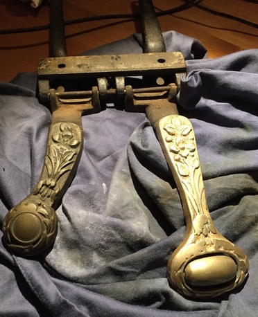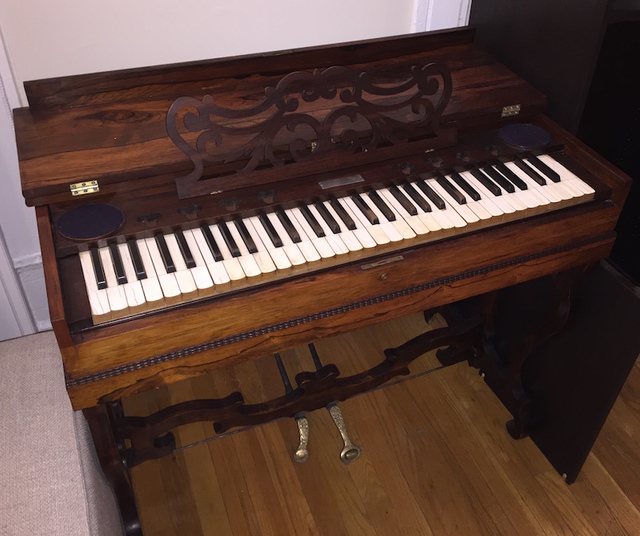
Back in September 2015 I got a MELODEON on Craigslist, and in the following several months I transformed it into a MIDI keyboard. A Melodeon is a smaller kind of American reed organ, usually having a single manual and no stops; the one I got is a Lyre-Leg Melodeon, pictured below (after restoration). Click here for the schematics and microcontroller code.
Here are some general resources about reed organs:
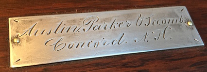
The organ i got was made by the firm of Austin, Parker & Secomb, of Concord NH. I tracked down some information regarding the company with limited success: besides a partial match on Gellerman's Atlas, I managed to date the organ's manufacturing date in the early 1870s (the firm was apparently active between 1871 and 1873 as can be seen in The New Hampshire Register, Farmer's Almanac and Business Directory).
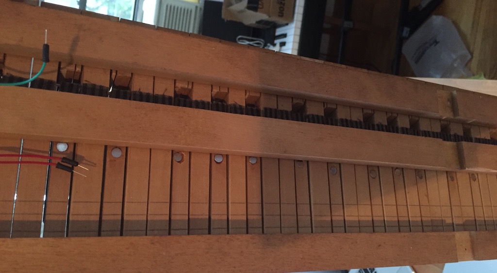
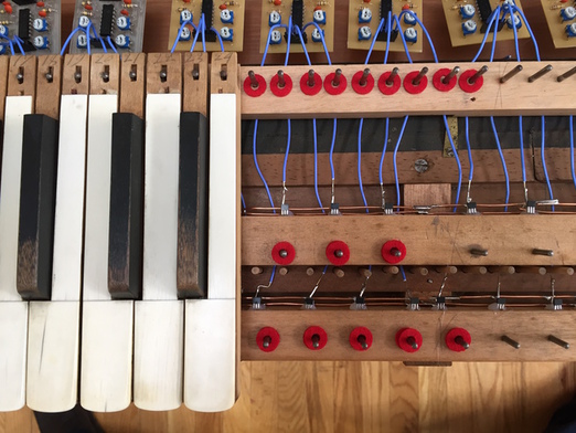
The overall circuitry is roughly split into two parts: measuring each key's up/down state, and converting the keyboard's global state into a MIDI stream.
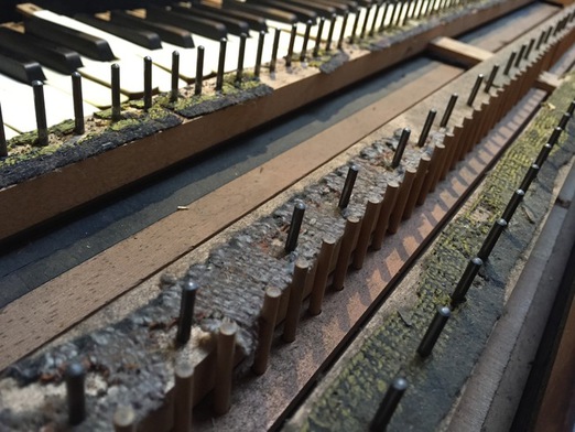
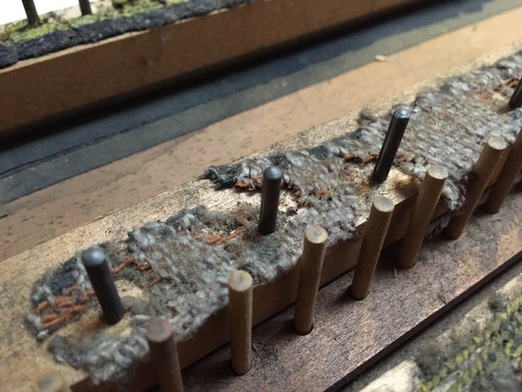
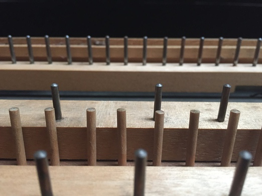
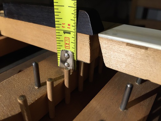
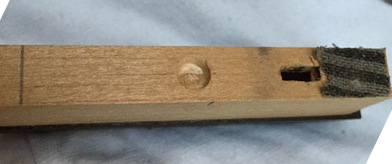
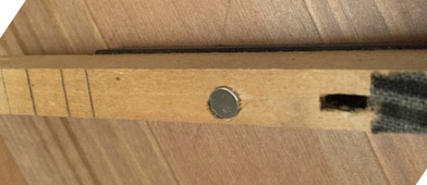
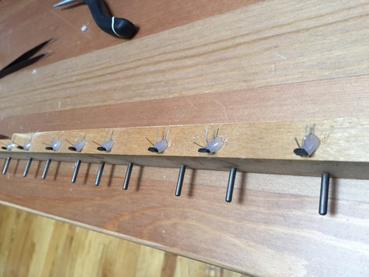
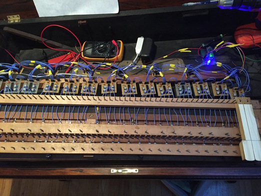
 The first part takes care of measuring the state of the keys
(pressed or not) at any time. To do so, a magnet is placed under
each key and its distance from the keybed is measured by means
of a Hall
Effect sensor (a device that varies its output voltage in
response to a magnetic field). The continuous output of the
sensors is then converted to a binary signal through the use of
a comparator.
The first part takes care of measuring the state of the keys
(pressed or not) at any time. To do so, a magnet is placed under
each key and its distance from the keybed is measured by means
of a Hall
Effect sensor (a device that varies its output voltage in
response to a magnetic field). The continuous output of the
sensors is then converted to a binary signal through the use of
a comparator.
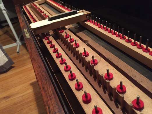
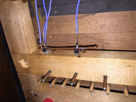
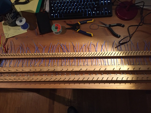
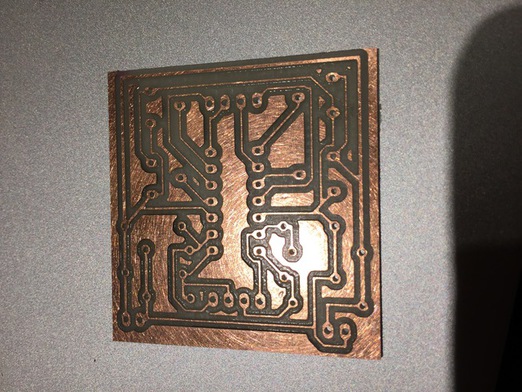
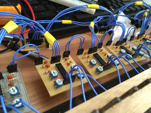
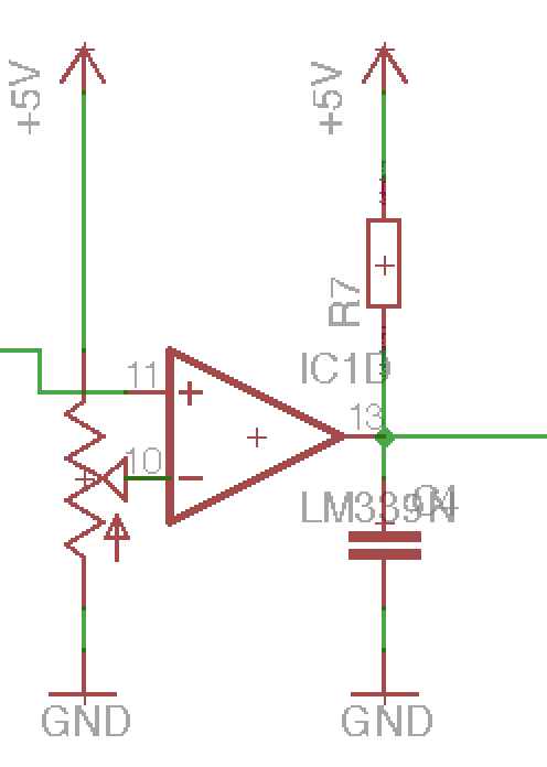
 I used AH3503 (linear) Hall Effect sensors and LM339
comparators; both are 5V-powered. The variable resistor that
feeds into the negative input of the comparator is used to set
the comparator's threshold; this allows one to set the distance
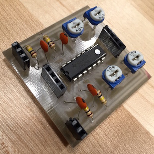
at which a key switches between the pressed/depressed state. The
board is pictured at the right: each chip has four comparators,
so each board processes four keys, while the other pin inputs are
for power.
I used AH3503 (linear) Hall Effect sensors and LM339
comparators; both are 5V-powered. The variable resistor that
feeds into the negative input of the comparator is used to set
the comparator's threshold; this allows one to set the distance
at which a key switches between the pressed/depressed state. The
board is pictured at the right: each chip has four comparators,
so each board processes four keys, while the other pin inputs are
for power.
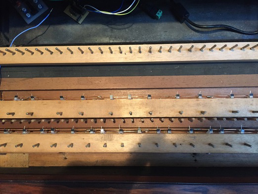
The second stage of the circuitry periodically captures a global snapshot of all the sensors' outputs at once and converts it into a serial stream which is fed into an Arduino microcontroller. The serialization is achieved through a series of Parallel Input Serial Output (PISO) Shift Registers chained together. Each shift register has an internal 8-bit memory that is set by reading 8 digital inputs in parallel (the key sensing circuit's outputs); multiple shift registers can be chained to form a single arbitrary-sized shift register.
The reason for using shift registers is that they enable multiple inputs (61 in this case) to be captured at once and subsequently read one-by-one in a serial fashion, thus needing only a few control lines to be attached to a microcontroller. This video provides a good tutorial on the inner workings of shift registers.
The microcontroller's job is then to periodically take a snapshot of all inputs, and read them back one-by-one while checking whether the state of each key has changed from the previous iteration; in that case a MIDI command (note on/off) is sent to a serial port connected to two GPIO pins on the microcontroller (the physical MIDI output port).